-
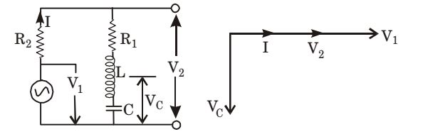
The circuit shown in the figure given below is energized by a sinusoidal voltage source V1 at a frequency which causes resonance with a current of I.
The phasor diagram which is applicable to this circuit is
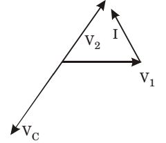
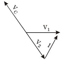
Correct Option: A
At resonance, voltage across L and C will be equal in magnitude and opposite in direction. So V2 is the voltage which is equal to the voltage across R1, and will be in the same direction of I and V1 be voltage across capacitor Vc will be lagging the current by 90°.
Thus, we have