-
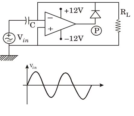
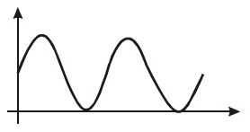
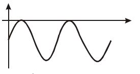
For a given sinusoidal input voltage, the voltage waveform at point P of the clamper circuit shown in figure given below will be
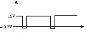
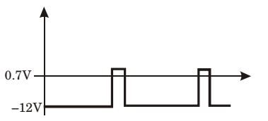
Correct Option: D
During the cycle of Vin , diode is cut-off and
VP = Vi Av = – VCC = – 12 volts
During -ve cycle of Vin, diode is ON,
Current through RL, iL = 0
Then, VP = VL + VD
= iLRL + VD = 0.7 volts

