-
Assuming the diodes D1 and D2 of the circuit shown in figure to be ideal ones, the transfer characteristics of the circuit will be

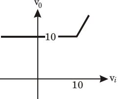
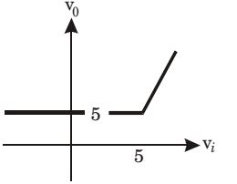
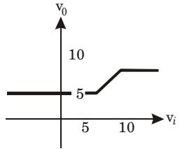
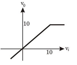
Correct Option: A
For Vi < 5 volts
D1 is OFF, D2 is ON then, the circuit will be drawn as,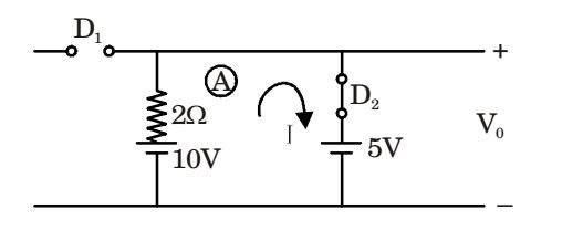
KVL in loop (A) gives,
10 – 2I – 5 = 0
⇒ I = 2.5 A
and V0 = 5 volts
For Vi > 5 volts, D1 is ON and D2 is OFF.
The circuit will be as shown below,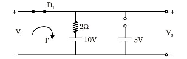
KVL gives,
| I' = | ||
| 2 |
and V0 = 10 + 2I' = 10 + Vi – 10
⇒ V0 = Vi
Hence, the transfer characteristics will be as shown in choice (b).

