Digital circuits miscellaneous
- The clock frequency applied to the digital circuit shown in the figure below is 1 kHz. If the initial state of the output Q of the flip-flop is ‘0', then the frequency of the output wave orm Q in kHz is X

-
View Hint View Answer Discuss in Forum
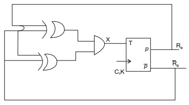
From above fig.
X = [(Q ⊕ Q).(Q ⊕ Q)]
X = 1 because
Q ⊕ Q = 1 always ⇒ Q ⊕ Q = 0 always
∴ (q ⊕ Q) . (Q ⊕ Q = (1 . 0) = 0 = 1
∴ ‘ T ’ input = 1 always for ‘τ’ flip flop of input = 1 then O/P will be implemented at the time of triggering.
∴ ƒ1 = 0.5(ƒ) = 0.5(1) = 0.5kHzCorrect Option: B
From above fig.
X = [(Q ⊕ Q).(Q ⊕ Q)]
X = 1 because
Q ⊕ Q = 1 always ⇒ Q ⊕ Q = 0 always
∴ (q ⊕ Q) . (Q ⊕ Q = (1 . 0) = 0 = 1
∴ ‘ T ’ input = 1 always for ‘τ’ flip flop of input = 1 then O/P will be implemented at the time of triggering.
∴ ƒ1 = 0.5(ƒ) = 0.5(1) = 0.5kHz
- A two-bit counter circuit is shown below. If the state QAQB of the counter at the clock time tn is "10" then the state QAQB of the counter at tn + 3 (after three clock cycles) will be

-
View Hint View Answer Discuss in Forum

Correct Option: C
- The figure shown a digital circuit constructed using negative edge triggered J-K flip flops. Assume a starting state of Q2Q1Q0 = 000. This state Q2Q1Q0 =000 will repeat after _______ number of cycles of the clock CLK

-
View Hint View Answer Discuss in Forum
First flip flop acts as mod-2 counter Second 2 flip flops from mod (2n-1) Johnson counter = mod counter
∴ overall modulus = mod – 6 counterCorrect Option: C
First flip flop acts as mod-2 counter Second 2 flip flops from mod (2n-1) Johnson counter = mod counter
∴ overall modulus = mod – 6 counter
- The truth table of a monoshot shown in the figure is given in the table below.

Two monoshots, one positive edge triggered and other negative edge triggered, are connected as shown in the figure. The pulse widths of the two monoshot outputs, Q1 and Q2. are TON1 and TON2 respectively.
The frequency and the duty cycle of the signal at Q1 will respectively be
-
View Hint View Answer Discuss in Forum
From question,
ƒ = 1 , D = TON2 TON1 + TON2 TON1 + TON2 Correct Option: B
From question,
ƒ = 1 , D = TON2 TON1 + TON2 TON1 + TON2
- Which of the following logic circuits is a realization of the function F whose Karnaugh map is shown in figure.

-
View Hint View Answer Discuss in Forum

F = AC + BC

Among all the options, option (c) is matching with function F = AC + BCCorrect Option: C
F = AC + BC
Among all the options, option (c) is matching with function F = AC + BC

