-
For the circuit shown below,
the CORRECT transfer characteristic is
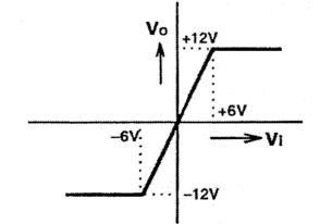
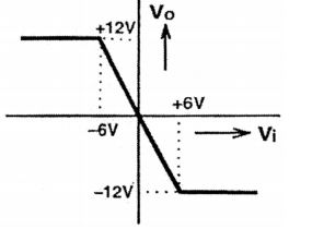
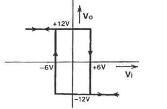
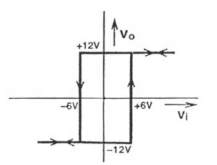
Correct Option: D
Redrawing the first stage,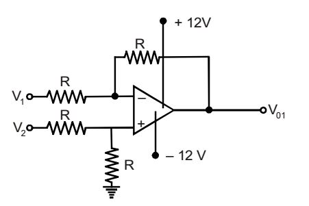
Assuming ideal OPAMP’s
| V- = V+ = | ||
| 2 |
| V+ = | = | ||
| R + R | 2 |
Using KCL at inverting terminal, we get
| = | ||||
| R | R |
⇒ V01 = 2V– – V1 = V2 – V1
= – Vi [as V1 – V2 = Vi]
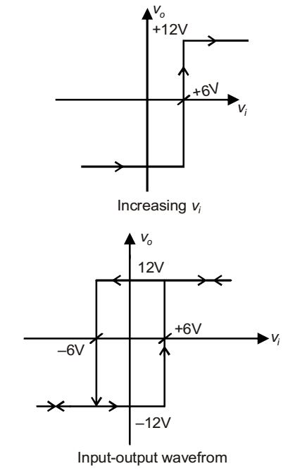
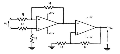
For the second-stage schmitt-trigger.
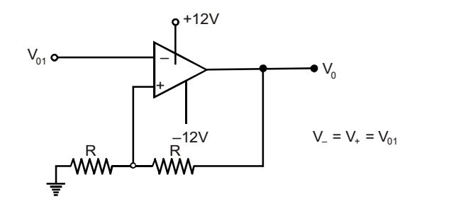
For V01 < V+ or Vi > V+, V0 = 12 Volts
| v+ = | VR + | V0 ≡ V1 | ||
| R + R | R + R |
As VR = 0 [VR is grounded]
| v+ = | ≡ V1 .......(A) | |
| 2 |
For v01 > v+
or vi < v+ , v0 = – 12 volts
The voltage at the non-inverting terminal is,
| v+ = | - | V0 ≡ V2 | ||
| R + R | R + R |
| v+ = - | ≡ V2 | |
| 2 |