-
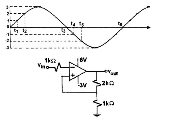
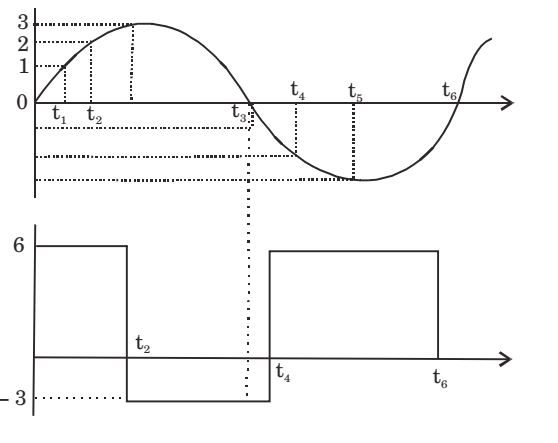
An ideal opamp circuit and its input waveform are shown in the figures given below. The output waveform of this circuit will be
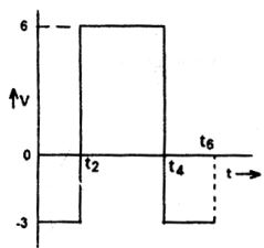

Correct Option: D

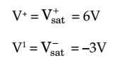
V0 = + Vsat , if V+ > V–
= – Vsat , if V+ < V–
| VA = | V0 = | |||
| 1 + 2 | 3 |
Vin ≃ VA ≤ 2 (for V0 = 6, upto t2)
After t2, Vout = – 3VA
| At t = t4 , VA = | (– 3) = – 1V (for V0 = – 3, after t4) | |
| 3 |
Hence after t4, Vout = 6V

