-
An electrical system and its signal-flow graph representation are shown in Fiures I and II respectively. The values of G2 and H, respectively, are

-
-
Z3(s) , -Z3(s) Z1(s) + Z2(s) + Z3(s) Z1(s) + Z3(s) -
-Z3(s) , -Z3(s) Z2(s) - Z3(s) + Z4(s) Z1(s) + Z3(s) -
Z3(s) , Z3(s) Z2(s) + Z3(s) + Z4(s) Z1(s) + Z3(s) -
-Z3(s) , Z3(s) Z2(s) - Z3(s) + Z4(s) Z1(s) + Z3(s)
-
Correct Option: A
Applying loop rules to both the loops,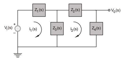
Vi (s) = I1 Z1 (s) + (I1 – I2) Z3 (s) ...(i)
I1 Z3 (s) = I2 Z2 (s) + I12 Z3 (s) + I2 Z4 (s) ...(ii)
From equation (i),
| = | + I1 .....(iii) | |||
| Z1(s) + Z3(s) | Z1(s) + Z3(s) |
From equation (ii),
| I2 = | ...(iv) | |
| Z1(s) + Z2(s) + Z3(s) |
From the given signal-flow graph, and from equation (iv), we get
| = G2 | ||
| I1 |
| ⇒ G2 = | ||
| Z1(s) + Z2(s) + Z3(s) |
From equation (iii),
| H = - | ||
| Z1(s) + Z3(s) |

