-
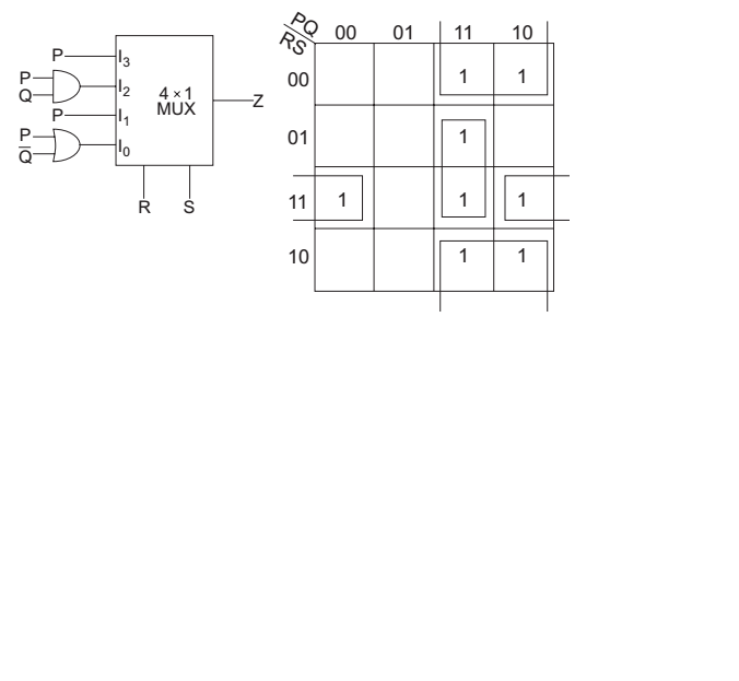
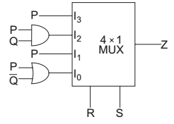
For the circuit shown in the following figure, I0 – I3 are inputs to the 4: 1 multiplexer, R (MSB) and P and Q are control bits. The output Z can be represented by—
-
- PS+ P Q S + R S Q
- P Q + PQR + P Q S
- P Q R + PQR + PQ R S + Q R S
- PQR+ PQRS + PQ RS + Q R S
Correct Option: A
The given circuit
Z = + R + SP + + RSPQ + R + SP + RS (P + + Q)
or
Z = + R + SP + + RSPQ + PR + S + PRS + + QRS
From above K-map, we get
Z=P + S + PQS + RS + Q