-
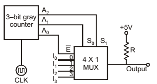
A 3-bit gray counter is used to control the output of the multiplexer as shown in the figure. The initial state of the counter is 0002. The output is pulled high. The output of the circuit follows the sequence
-
- I0, 1, 1, I1, I3, 1, 1, I2
- I0, 1, I1, 1, I2, 1, I3, 1
- 1, I0, 1, I1, I2, 1, I3, 1
- I0, I1, I2, I3, I0, I1, I2, I3
Correct Option: A
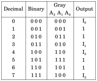
A0 is mapped to E of 4 :1 MUX it means when A0 (E) will be low then MUX will be enabled and as per S0 (A1) and S2 (A2) will produce the output and when A0 (E) will be high then 4 :1 MUX will be disabled and disabled output will be 1.

