-
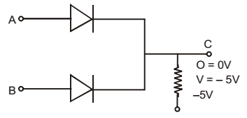
If negative logic is used, diode gate shown in the given figure will represent a/an
-
- OR gate
- AND gate
- NOR gate
- NAND gate
Correct Option: B
When either A or B or both are at zero potential, current flows through R, thereby bringing the potential of C to zero level, Thus logic output is zero. When both of them are at 5V no current can flow and voltage of C stays at – 5V, i.e. logic output of 1.
Thus it is AND gate.

