-
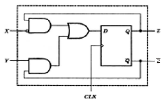
A sequential circuit using D flip-flop and logic gates is shown in the figure where X and Y are the inputs and Z is the output. The circuits is z
-
- S – R FF with inputs X = R and Y = S
- S – R FF with inputs X = S and Y = R
- J – K FF with inputs X = J and Y = K
- J – K FF with inputs X = K and Y = J
Correct Option: D

Comparing from the truth table of J– K FF
Y= J, X = K

