-
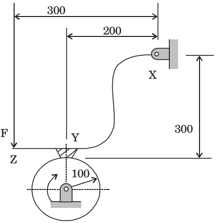
The schematic of an external drum rotating clockwise engaging with a short shoe is shown in the figure. The shoe is mounted at point Y on a rigid lever XYZ hinged at point X. A force F = 100 N is applied at the free end of the lever as shown. Given that the coefficient of friction between the shoe and the drum is 0.3, the braking torque (in Nm) applied on the drum is _____ (correct to two decimal places).
-
- 8.12
- 8.24
- 8.18
- 9.15
Correct Option: C
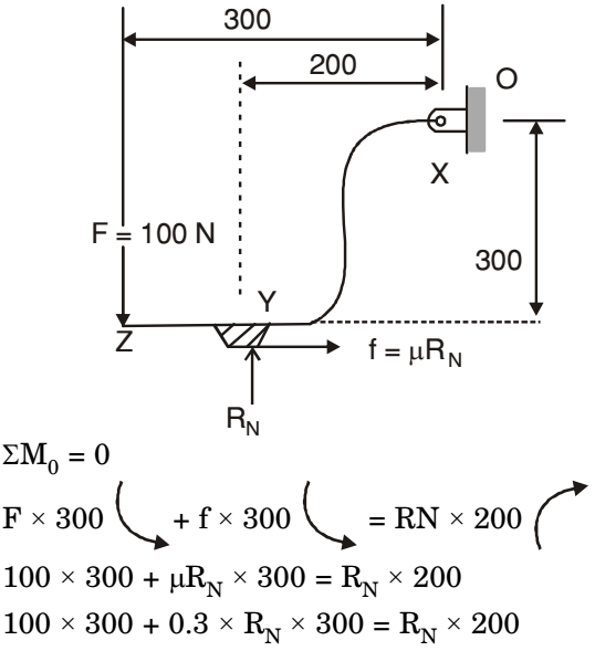
300 = 1.1 RN
RN = 272.72 N
Braking Torque = μRN × R
= 0.3 × 272.72 × 0.100 = 8.18 Nm

